I decided to start with ignition first since that seems to be the hardest to get a handle on, at least for motorcycles anyway, based on what I've read in the forums. And man have I
So here's what I've got going so far:
I went with a 36 tooth wheel to keep timing accuracy. I feel this is especially important for a lower RPM thumper like the DR650. And I can tell you it has made a huge difference in my bike compared to the stock CDI. It runs so much better down low when the engine is just thumping it's amazing. Fuel econmy has jumped up from 54 mpg to over 57 mpg without touching the carb in any way. Gotta love that spark advance table (the stock Suzuki CDI is a dumb RPM only advance).
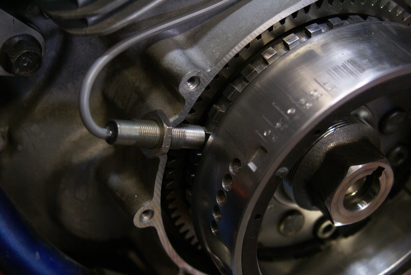
I used a Hamlin 55075 12mm gear tooth hall sensor http://www.hamlin.com/technical-detail-hall-sensor.cfm and made a 36/1 tooth wheel out of the stock extra flywheel weight Suzuki attaches to the back of the rotor. This for me was easier than trying to dink around using the stock VR and it allowed me to figure out the stock timing advance (which Suzuki does not publish) and match up the trigger settings by running the bike on the stock CDI while watching the µs in action off to the side.
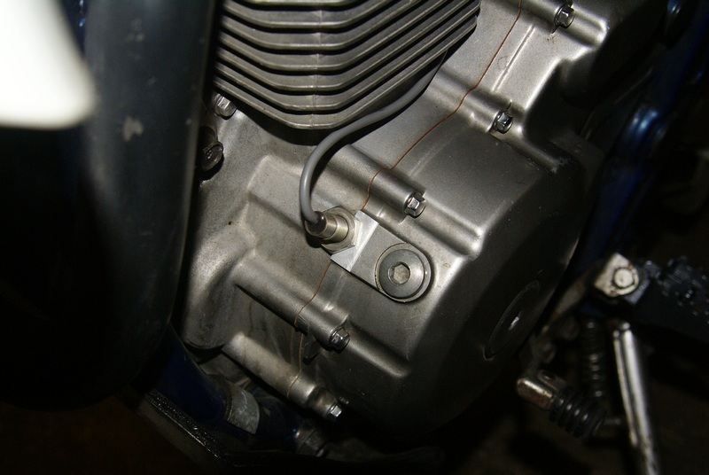
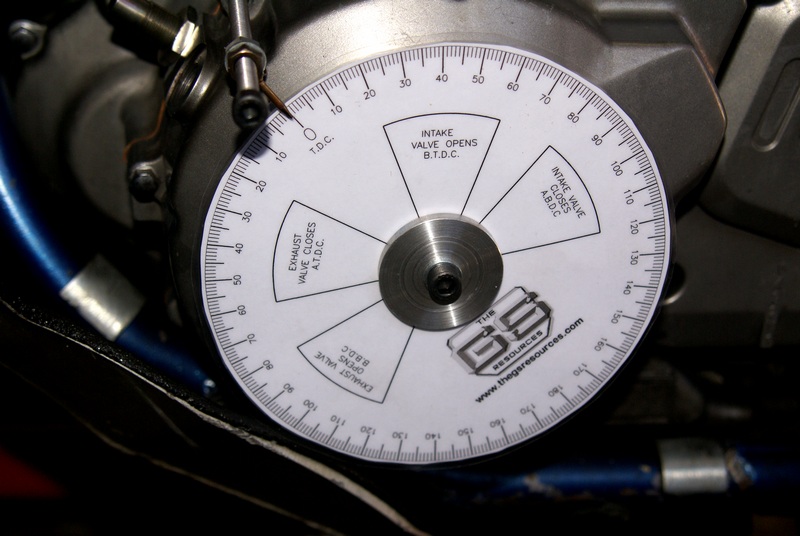
I built this degree wheel set-up so I could figure out what the stock Suzuki timing curve looked like for a good starting point:
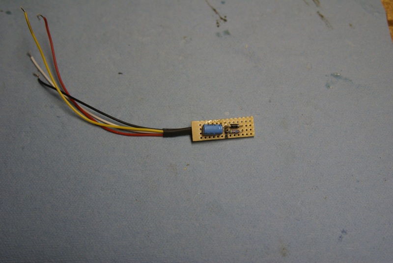
Next was to make the µs understand what the Hamlin was telling it. That took some dinking around but the final verdict is use VR1 with Bruce's hall offsetter circuit. http://microsquirt.com/viewtopic.php?f=87&t=22790 I could never get more than 5800 RPM out of opto without resets after trying a ton of different resistors. No matter... VR1 with the offsetter circuit runs well past my 8k red line with no issues. Here's my rendition before I potted it with electronics epoxy:
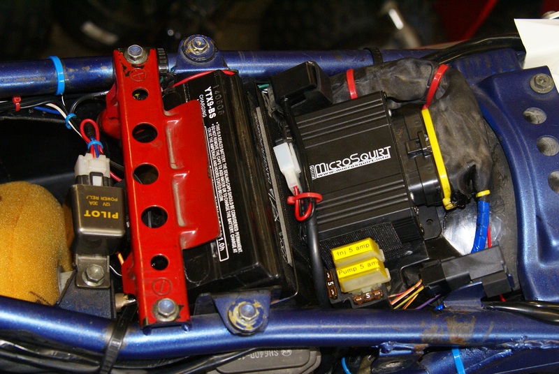
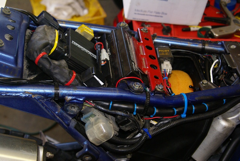
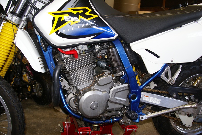
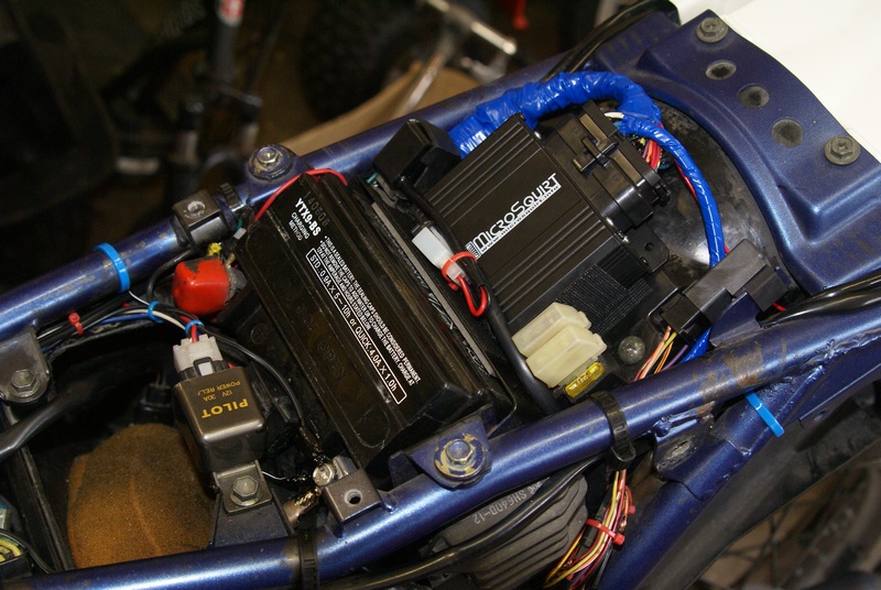
The µs fits nicely where the stock CDI once mounted. I had to whack off the mounting flange opposite the connector to get the µs as close to the battery box as possible for seat clearance. The µs is mounted with industrial velcro on the bottom and against the battery box. This added a bit of vibration isolation. I still ended up spacing the inner fender front mounting position down another 5/16 of an inch to keep the plastic seat pan from resting on the µs.
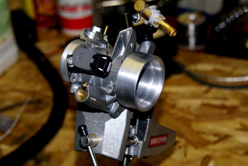
I'm using the TB and related components from a Suzuki LT-R450 fourwheeler. The TB bore is 42mm so it is not too oversized for the lower RPM big bore engine (the stock carb is 40mm). This is the R450's TB after I modded it to fit in the same physical space as the stock Suzuki carb (or the FCR-MX that I have on my bike now). I machined the nose OD to fit into the stock Suzuki intake manifold and turned an aluminum adapter for the intake bell to work with the stock air boot.
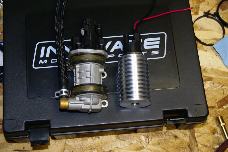
The R450's fuel pump has a super low current draw which is great for the DR650's limited 200 watt stator. Here it is sitting next to my first FP rendition on the right (Toyota Camry pump + my machined housing) which ended up drawing way too much current for my bike's anemic charging system. I'm also using the R450's fuel pressure regulator and using my California model DR650's charcoal cannister return line on the fuel tank to return the excess fuel. The return line will also serve to flood the pump hosing and vent off any trapped air before reaching the pump.
I still need to figure out a swirl tank... the stock R450's is way too big for the room I have so I'm thinking of making a vented fuel filter serve a dual purpose as a swirl tank. That should slow fuel velocity down enough to allow trapped air to escape and give the pump an extra reservoir of fuel.

I bought a complete wiring harness for the R450 off ebay for all the water proof connectors and it even came with the FP relay, MAP, IAT, CLT mini dual circuit fuse box for the FP/Injector and all the extra wiring and harness protectors I could use after dissecting the harness.
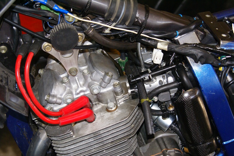
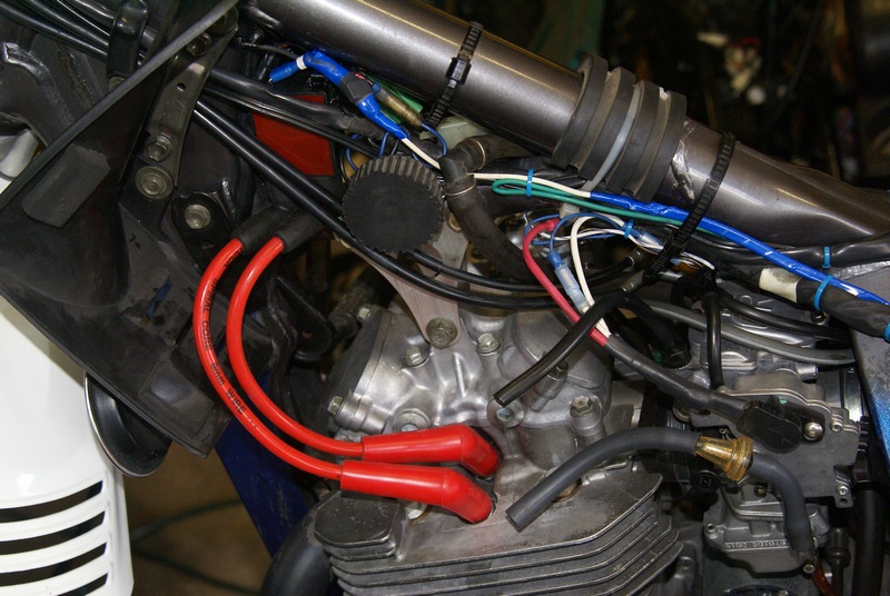
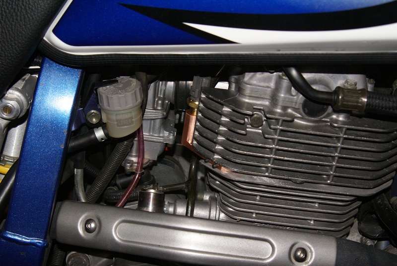
For a coil I went with a Nology PFC-06D .6 ohm dual tower. http://www.nology.com/profiremotor.html It's small size made it a nice fit in the DR650's tight quarters. Yeah, the DR650 has twin plugs.
I have my sequential cam sensor finished and working... well, it works on an oscilloscope.... and VR1 with the offsetter circuit... and opto with a pull up resistor.
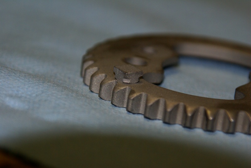
Here's the single cam tooth target I put on the cam sprocket. Just misses the chain and everything else in the cylinder head cap.
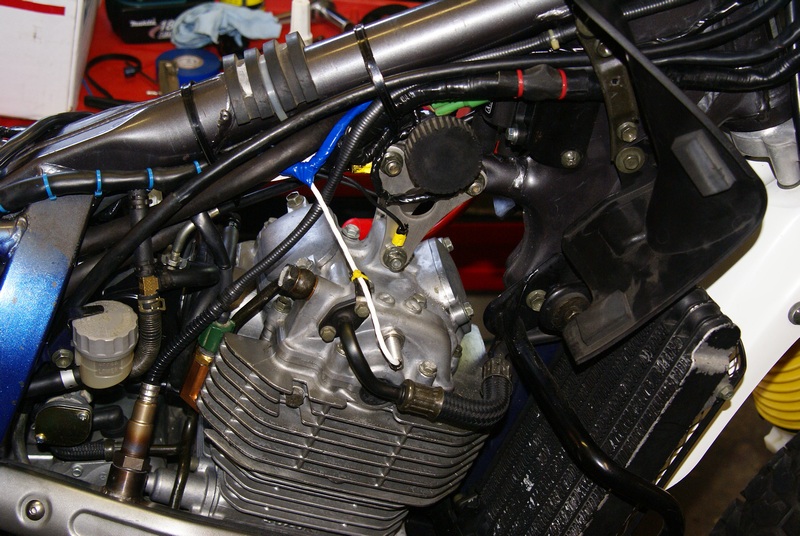
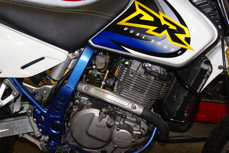
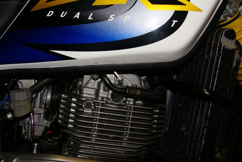
I made a copper engine temp assembly using the stock R450's temp sending unit (it's water cooled) to fit between the head and barrel of my air cooled bike. Not sure how but the thing works perfect... It looks like I won't even need to use the extended CLT range in the µs set-up as it is running right between 175 and 196 degrees at various speeds. If I run into trouble later for some reason, like cold weather riding, I'll switch over to the spark plug ring sender and turn on the extended clt range.
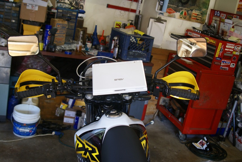
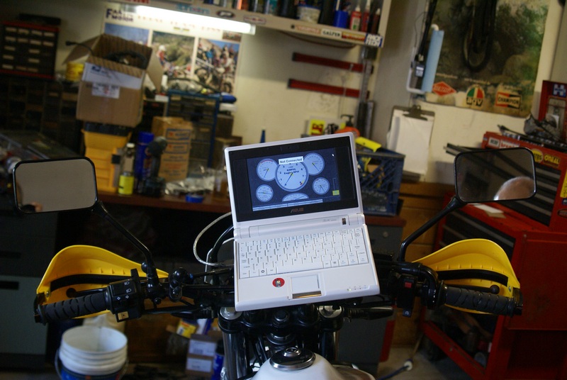
I was not enamored by the thought of having to go out for a data log session and then drive back to the shop to hook up to a PC to make changes. Soooo, the little Asus Eee-pc netbook's have hard cards instead of an actual hard drive with moving parts which I felt might die from the thumper's vibration. With 4GB of drive space it's more than enough for Windows XP, TS, Megalog Viewer, etc. I just pull over, open the netbook and make some adjustments and I'm back on my way logging. I see them all the time on ebay for $100 or less. Perfect communication with µs (with a Prolific USB to serial cable)... no resets or any funny business while data logging. I have it mounted on a RAM ball set up http://www.ram-mount.com/CatalogResults ... fault.aspx connected to the lower right handlebar clamp bolt. I just fabricated a sheet metal tray that the PC slides into nice and firmly .
Now it's time to hit fuel hard! I have just about all the components I need to put the system together except adapter mounts for the fuel pump and fuel pressure regulator. I have to tear out the carb to do some measuring so I can build those but I wanted to bask in the glow of my bike running on µs ignition this weekend before ripping it all apart again.
Stay tuned!